
 MENU
MENU
CT - CENTRALTEST
| Datasheet: | Download |
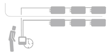
The emergency operation of luminaires is activated automatically when the voltage supplying these luminaires is lost. All the devices in the system are supplied with power from 230VAC power grid.
The elements of this system are connected with a communication wire, and each device has its own address. The efficiency tests can be carried out at the level of the central control unit on the luminaires and other functions:
• TEST A – short one minute test of the luminaire working condition which must be carry out once a month,
• TEST B – testing emergency operation time which must be carried out once a year,
• TEST C – testing the communication of emergency operation locking,
• Night mode – automatic activation of luminaires at specific time (operation from the network, not from the battery).
CENTRALTEST system is popular in medium-sized and large buildings where central monitoring is the only way to supervise effectively so many emergency luminaires, e.g. hotels, schools, hospitals, shopping centres, office buildings, industrial buildings, stadiums, railway stations.
The principle of the system is to use emergency luminaires equipped with individual batteries and the microprocessor system with the possibility of communicating in the CT technology.
All the information on the system condition may be read from the control units or saved as a report.
Apart from luminaires and control units for the CENTRALTEST system, we also offer expanders, that is appliances enabling the connection of more luminaires and extending maximum distance between the control unit and the luminaire.
CENTRALTEST system functionality depends on the control unit:
| control unit version | ct communication | ct-bus communication | ct-loop communication | software pc-4 visualisation browser access | dynamic system | hvcbs/lvdbs connection | bms connection |
| H-302C Control Unit - The simplest solution which allows monitoring up to 7936 luminaires, connect BMS and servicing by means of a touch screen | YES | YES | |||||
| H-312 Control Unit - The most extended solution ensuring practically unlimited possibilities, including: Monitoring of CT luminaires and HVCBS and LVDBS systems supplied with power centrally, visualisation of installations and localisation of devices, servicing of DYNAMIC luminaires and connection to BMS and SSP. Control unit is serviced by means of a large touch screen or remotely through the Internet browser | YES | YES | YES | YES | YES | YES | YES |
| Computer set - Solution cheaper than H-312 where we provide the pre-configured PC set, software and special interface for communication with the luminaire network. This option excludes supporting DYNAMIC and SSP luminaire and provides functionality identical to H-312 | YES | YES | YES | YES | YES | ||
| Software PC-4 on your own computer. The most convenient solution, when we have a PC or server, which may be used as a control unit. In this case, we buy software, communication interface and installation service. This functional solution does not differ from the option with a preconfigured computer set | YES | YES | YES | YES | YES |
COMMUNICATION WIRING
• For communication in system should be used cable, e.g. HTKSHekw 1x2x0.8 type (2 core twisted pair cable). Note: Make sure that the cable type is in accordance with the design and current regulations
• The communication line signals are labelled with the following letters: A, B and E. They are led out to the connectors of interface, expander and luminaire
• A and B signals must be led in a strand line, and E signal must be connected to the cable screen
• When performing the communication line installation, it is important to ensure the connection continuity of the screen and each signal, A and B, between all the system elements
• It is required to ensure the PE signal continuity between all the system elements
• It is not permitted to connect the communication line screen cable with the PE signal.
COMMUNICATION TECHNOLOGIES
CENTRALTEST System makes use of 3 different communication technologies which determine the connection manner, wires types, addressing technique and maximum quantities of appliances. In one installation it is possible to use various communication technologies, combining them by means of a proper expander. Technology may be changed from CTL to CTB and CT or from CTB to CT. All the technologies are based on EIA/TIA-485 and author’s communication protocol.
CT communication
Currently, all the luminaires, apart from the dynamic ones, make use of the communication technology. Appliances are connected in series in the bus topology and depending on the appliance type we may connect max 64 luminaires or 31 expanders on a single communication line. Each appliance on the line must have a unique number within the range from 1 to 64 for luminaires and from 1 to 31 for expanders. Numbers are allocated in the manufacturing process in accordance with the project or directly by means of a manual numerator during installation in the building. Maximum length of lines - 1000m.
Expanders may not be connected with one another in series and in parallel with luminaires.
CT-BUS communication
In this technology, expanders H-311, interface H- 310 and control unit H-312 may operate.
As with the CT technology, in the CT-BUS, appliances are connected in the bus topology. CT-BUS enables connection of max 128 appliances in a single line with the max length of 1200m. The appliances in this communication technology have a unique serial MAC address which is used for communication, what eliminates a necessity for assigning addresses during installation and communication problems resulting from their duplication. Unlike CT, it is possible to join max 7 expanders in series. It may be used for amplifying a signal or for non-typical line branches.
CT-LOOP communication
This communication technology is dedicated mainly to systems with dynamic luminaires.
CT-LOOP is communication in the loop topology with bidirectional short-circuiting insulation, which increases resistance to damage. A superior appliance is capable of detecting a network segment which is not operating (and indicate the appliances in the loop) and change the communication route from the one side of the loop to the other. As with CT-BUS, in the event of CT-LOOP, each appliance has a unique serial MAC address used for communication. CT-LOOP admits max 64 appliances in the loop with max 7 expanders between the control unit and luminaires. Max total line length for a single loop is limited to 1200 m. H-311 CTL expander may also be applied for conversion between CT-LOOP and CT-BUS. Each appliance operating in the CT-LOOP technology is equipped with at least two connectors for communication between which a coupling transmitter is mounted. When communication is lost, each device located in the loop disconnects it by opening a transmitter and then a superior element (control unit, expander) re-couples the loops, separating the damage location, at the same time signalling the appliances to the user between which a wiring segment was damaged.