
 MENU
MENU
HVCBS
| Karty produktu: | System: HVCBS Central unit: One-section housing Two sections housing Fireproof housing Housing with increased tightness to IP65 Mounting plate Substation: One-section housing Two sections housing Fireproof housing Housing with increased tightness to IP65 Mounting plate Manual: HVCBS |
Emergency and evacuation lighting luminaires connected to the Central Battery System are located in end circuits. Communication with luminaires takes place by means of the power supply line.
A controller with a touch display has a simple and intuitive interface and it allows for fast system configuration. Automatic performance of tests in accordance with EN 50172:2005 from the controller level. Both test results and reports on errors and failures are saved and kept on the internal SD card. It is also possible to save test results and reports on errors and failures on the external USB memory. Such a solution facilitates
reporting and keeping the Incident Log (in accordance with EN 50172:2005).
HVCBS uses hermetic and maintenance-free batteries paired in terms of internal resistance and voltage what allows for long-term correct operation. The selection of batteries depends on loading and system operation time during emergency operation.
A temperature probe monitors temperature in the battery. The system has the signalisation of batteries discharging in accordance with EN 50171:2007.
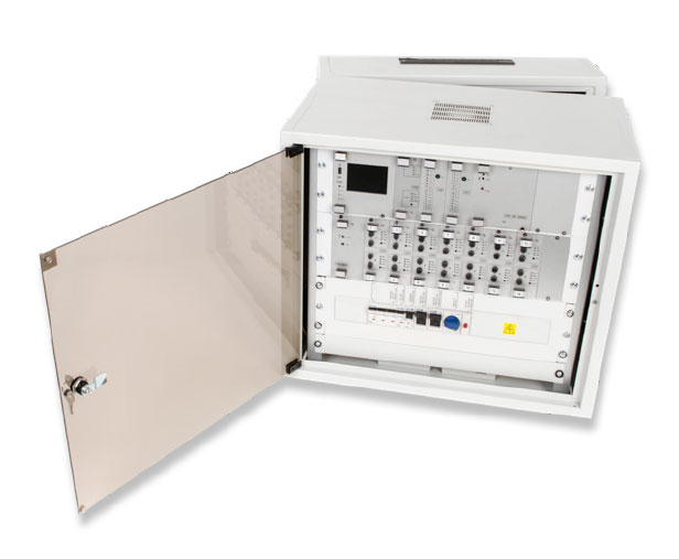
The use of dedicated safety devices for circuits, automatics and batteries affects the increase in the safety level. HVCBS System is dedicated to supply the emergency and evacuation lighting circuits in the IT network in the battery mode.
Central unit housing types:
 One-section housingTwo sections housingFireproof housingHousing with increased tightness to IP65Mounting plate
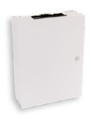
Battery housing types:
• Cabinet
• Rack
• Fireproof cabinet
FEATURES
• Power supply voltage: 3x230V AC
• Output voltage: 230V AC or 220V DC
• Max power of reception: 16kW (see following table)
• Touch LCD with user-friendly menu
• Automatic performance of tests, acc. to EN 50172:2005
• Safe test result to SD card, acc. to EN 50172:2005
• Possibility of the individual configuration of access to the system
• Monitoring the presence of voltage from basic lighting switching stations, acc. to EN 50172:2005
• Possibility of extending the system with substations (up to 32)
• Max 64 circuits for one system unit (see following table)
• Monitoring luminaires or circuits
• Communication with luminaires by means of a power supply line
• Configuration of luminaires operation modes, maintained/non-maintained
• System compensating current surge at switching the lighting on
• Hot swap technology
• USB socket
• Ethernet socket
• EIA/TIA-485 connector
• Cooperation with BMS
• Cooperation with back-up power supply systems
• Lockout function
• 10 years lifespan battery
• Battery discharging signalisation
• Temperature probe.
TECHNICAL DATA
Data depends on system implementation.
| One-section housing | Two sections housing | Fireproof housing (EI30, EI60, EI90) | IP65 housing | Mounting plate | |
| Power supply | 3x230V AC | 3x230V AC | 3x230V AC | 3x230V AC | 3x230V AC |
| Frequency | 50Hz | 50Hz | 50Hz | 50Hz | 50Hz |
| Network type | TN-S/IT | TN-S/IT | TN-S/IT | TN-S/IT | TN-S/IT |
| Power of reception | ≤ 1,5kW / ≤ 0,5kW | ≤ 1,5kW / ≤ 0,5kW | ≤ 5kW / ≤ 2,4kW | ≤ 5kW / ≤ 2,4kW | ≤ 5kW / ≤ 2,4kW |
| Emergency operation time 1) | 1h / 2h | 1h / 2h | 1h / 2h | 1h / 2h | 1h / 2h |
| Battery capacity | ≤ 40Ah | ≤ 134Ah | ≤ 40Ah | ≤ 40Ah | ≤ 40Ah |
| Number of circuits | ≤ 16 | ≤ 64 | ≤ 32 | ≤ 32 | ≤ 32 |
| Number of potential-free inputs 2) | 5 | 5 | 5 | 5 | 5 |
| Number of relay outputs 4) | 4 | 4 | 4 | 4 | 4 |
| Panel ext4) | 1 | 1 | 1 | 1 | 1 |
| Number of substations 4) | ≤ 32 | ≤ 32 | ≤ 32 | ≤ 32 | ≤ 32 |
| USE 4) | 7 5) | 7 5) | 7 5) | 7 5) | 7 5) |
| USO ext4) | ≤ 16 6) | ≤ 16 6) | ≤ 16 6) | ≤ 16 6) | ≤ 16 6) |
| Protection class | I | I | I | I | I |
| Ingress protection | IP20 | IP20 | IP54 | IP65 | - |
| Dimensions (width x height x depth) [mm] | 604-871 x 600 x 400 | 337-1965 x 600 x 500-600 | 1080-1300 x 860 x 400 | 1000-1200 x 800 x 300 | 800x800, 1290x770 |
1) 3h – special variant
2) maximum number of potential-free inputs = 29
3) number of information outputs (BMS)
4) additional option
5) the total number of USI + USE modules cannot exceed 7 (56 potential-free contact inputs)
6) the total number of circuits cannot exceed 64
SYSTEM CONSTRUCTION
The system structure is made in 19-inch standard, which includes the following modules:
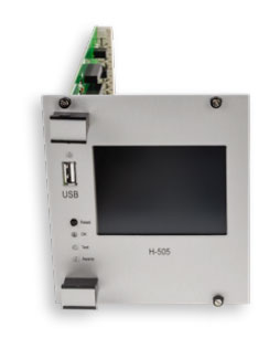
H-505 module is the main control unit in the HVCBS system, its main functions include:
• Monitoring and control of all internal system components
• Communication with substations
• Communication with Building Management Systems (BMS)
• Local interface based on the colour TFT LCD touch screen
• Automatic testing in acc. with the EN 50172:2005
• Saving tests results on SD card
• Saving tests results and settings on USB stick.
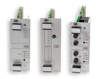
UKN module – allowing the measurement of parameters such as battery voltage, battery charging and discharging, load current and insulation state monitoring.
USI module – with potential-free contact inputs and relay outputs. Potential-free contact inputs may be paired with any lines and control them.
USO module – checking the condition of the luminaires in the final circuit. A single module allows to connect two final circuits.
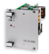
Rectifier – used for battery charging, designed according to the EN IEC 62485-2:2018-9 standard. Owing to solutions adopted in the module, current surge after connecting to the network is ensured. Output specification of the rectifier with impulse output current limitation of the constant voltage-constant current type. It has over-voltage protection at the level 110-120% of nominal voltage (infinitely variable adjustment). Output voltage adjusted to temperature changes according to the requirements of batteries manufacturers.
External modules allows to extend the system capabilities:
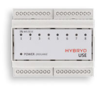
USE module – external module allowing for extending the system with 8 additional inputs of potential-free contacts. Potential-free contact inputs may be coupled with any circuits and controlled. It is possible to select the mode of inserting potential-free contact inputs (short-circuiting, opening controlled input, impulse controlled input). HVCBS may be extended max to 56 inputs of potential-free contacts.
USO ext – it is an external module allowing for extending the Central Battery system with additional 4 end circuits. This module as USO module allows for controlling end circuits. Owing to a small size and ergonomic shape, it may be installed in places where the use of a sub-station is not possible. An additional asset of this appliance is economy resulting from fewer lines.
USE voltage module – external module allowing for extending the system with 8 additional inputs of potential-free contacts. Potential-free contact inputs may be coupled with any circuits and controlled. The module detects a power failure/power outage. The total number of additional USI + USE modules cannot exceed 7. PW-01 module – allows for remote control of HVCBS condition. Basic parameters, such as voltage, current, operation mode, information on errors, tests and operation state is displayed on a transparent modern LCD.
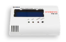
PW-01 module – allows for remote control of HVCBS condition. Basic parameters, such as voltage, current, operation mode, information on errors, tests and operation state is displayed on a transparent modern LCD.
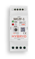
Bus connected phase control module MCZF-1 allows you to monitoring of the presence of three-phase voltage. The PSCL (Power Supply & Communication Line) allows for the parallel connection of many sensors in a star, bus or mixed topology. It saves communication cable, by using the two-wire (communication and power) line. It is an alternative to additional USI modules and standard phase control sensors connected by separate cables. Each module has its own individual address, set using the switches. It is possible to address 61 sensors.
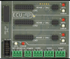
ECU (External Communication Unit) is a module used to isolate and separate the internal communication of the system. It allows you to connect up to three additional communication modules (UART or PSCM) that allow you to connect up to 64 external lines and up to 61 MCZF-1 modules.
PSCM (Power Supply & Communication Module) is a module that allows you to connect MCZF-1 phase control sensors or a battery control system. It can be placed in a free port of the H-505 unit or ECU module.
COMMUNICATION
Communication between the main station, sub-stations and external modules takes place by means of EIA/TIA-485 bus. The communication line uses 2 wires shielded twisted pair, e.g.. HTKSHekw 1x2x0,8.
In HVCBS the working order of luminaires may be checked through line control (end circuit current measurement) or through the individual control of luminaires with the use of address modules. Communication with luminaires takes place along the power supply line, the system does not require a separate communication line.
The communication of the main station controller with H-312 Control Unit or computer set takes place through the Ethernet connector and allows for extending HVCBS with remote monitoring and convenient management.
HVCBS controller (e.g.. H-505) cooperates with BMS (Building Management System) by means of MODBUS TCP/IP or RTU protocol and with back-up power supply systems. System configuration allows for monitoring the presence of voltage from basic lighting switching stations in accordance with EN 50172:2005.
NETWORK TOPOLOGY
