MENU
MENU
LVDBS
| Datasheet: | Download |
Low Voltage Distributed Battery System enables to supply emergency and evacuation lighting luminaires. The system consists of the LVDBS unit (which contains control, monitoring and power supply electronic systems with batteries) and luminaires connected to it. System is designed in accordance with EN 1838, EN 50171, EN 50172 and EN 62485-2.
FEATURES
• User-friendly menu
• State signalisation from each line
• Small system size
• SELV network
• Possible configuration of each line in the lighting mode, door holders (electromagnet) and signalling (horn or flash)
• Possible creation of fire signalisation scenarios for respective lines
• Automatic performance of tests in accordance with EN 50172
• Possibility of connecting circuits controlling the system operation
• 4 inputs controlled by potential-free contacts
• Possibility of connecting the informative and signalling system
• 3 outputs (system deactivation signalisation, battery operation signalisation, failure signalisation)
• Possibility of the system history preview and loading history to the external USB memory
• Possibility of generating reports and saving them in the external USB memory
• Ethernet socket
• Cooperation with BMS.
Emergency operation time is one, two or three hours (special variant). Hermetic maintenance-free batteries with the lifespan of 10 years are used.
It is dedicated to operation:
• At input voltage of 230V AC
• At output voltage of 24V DC.
During normal operation, the output voltage is obtained directly from the power supply, powered from the power grid, which additionally charges the batteries. During a power failure, the system goes into emergency mode and the 24V output voltage is obtained from batteries.
This type of system is intended for small buildings or where the replacement of autonomous luminaire batteries would generate high costs (e.g. due to the mounting height of luminaires), and the use of HVCBS system would not be profitable.
TECHNICAL DATA
| Power supply | 230V AC |
| Connection power | 500VA |
| Power load on one circuit1) | 75W |
| Number of circuits | 4 |
| Output voltage | 24V DC |
| Buffer voltage level | 27,2V |
| Ambient temperature | 15°C – 25°C |
| Emergency operation time | 1h / 2h / 3h |
| Battery capacity | 20Ah / 40Ah / 65Ah |
| Weight | 15kg / 27kg / 60kg2) |
1) measured on LVDBS unit terminals
2) LVDBS cabinet + cabinet with 65Ah batteries
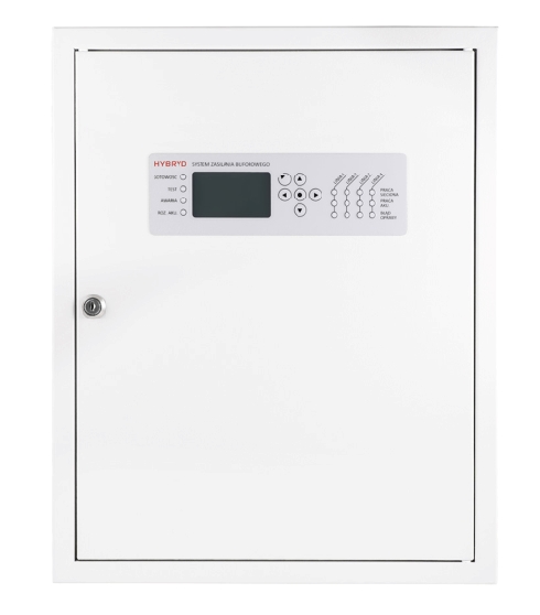
LVDBS UNIT
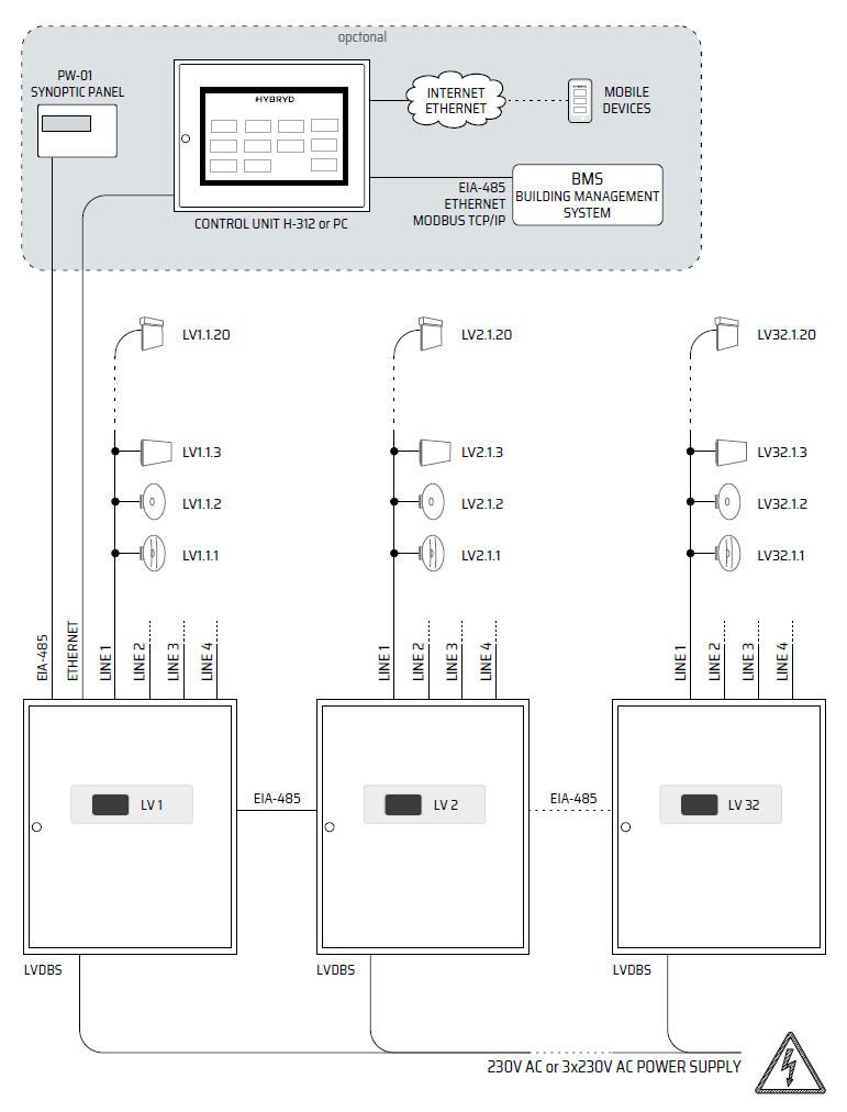
LVDBS units are equipped with a microprocessor controller with display and press button membrane panel. The controller is responsible for controlling the system operation and for communication with Control Unit or computer set through TCP/IP connector ETHERNET. Communication between cabinets enables you to view system results and states by means of the main unit.
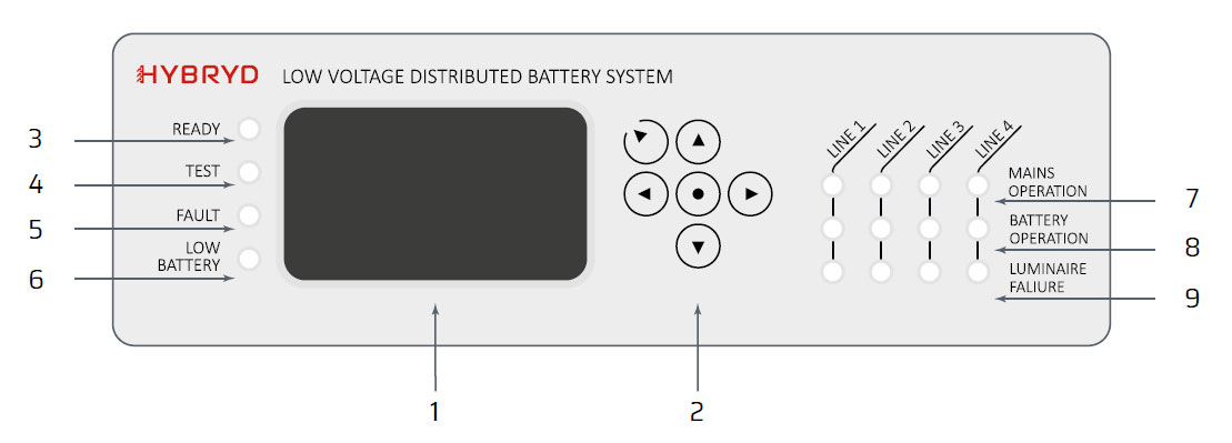
1. Display
2. Menu navigation buttons
3. LED indicating the correct system operation
4. LED indicating test execution or system battery operation
5. Error LED
6. LED indicating battery discharge below 19V
7. LEDs indicating the presence of voltage on the line
8. LEDs indicating battery operation (maintained mode)
9. LEDs indicating failure on the line
COMMUNICATION
The system may consist of 32 units connected through EIA/TIA-485 connector but operating independently. A communication line uses 2 strands led in a screen, e.g. HTKSHekw 1x2x0.8 Communication with luminaires supplied with the voltageof 24VDC takes place though lines power supply. Address modules are used for individual luminaires control. LVDBS can also be expanded with the PW-01 module, which allows you to remote control of the system status. Basic parameters such as voltage, current, operating mode, information on errors, tests and operating status are displayed on a clear, modern LCD display.
NETWORK TOPOLOGY