 MENU
MENU
DYN - DYNAMIC
| Datasheet: | Download |
DYN system is the element of CENTRALTEST system and it is characteristic for the use of PARK DYN type luminaires.
The evacuation lighting dynamic system is designed for the safe evacuation of people staying in the buildings with extended communication infrastructure.
It is integrated with fire signalling systems and it receives information on the location of a fire hazard, and then, by means of dynamic lighting luminaires, it indicates an optimal escape route. Such a route is indicated depending on the hazard location based on many scenarios pre-defined in the system.
FEATURES
• The ability to control and monitor dynamic emergency lighting luminaires
• System status reporting in accordance with applicable standards
• Communication with BMS
• Communication with SSP
• Construction and implementation of own evacuation scenarios
• Automatic control unit configuration with XML file
• Easy-to-use web application
CONNECTION
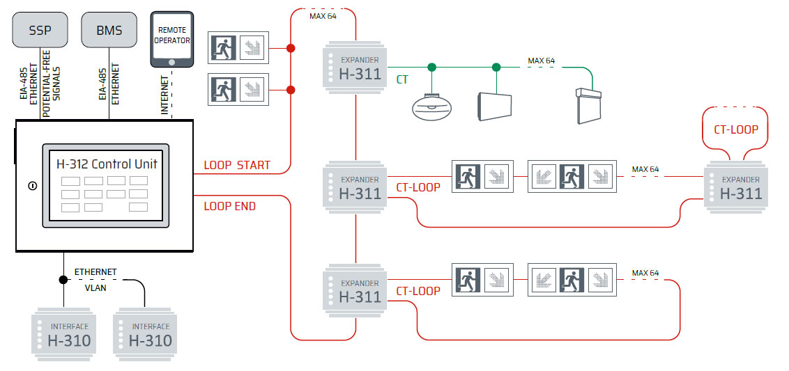
Dynamic luminaires may be connected with static luminaires to one H-312 control unit or they may have a separate independent control unit. DYN luminaires require loop communication – they have two connectors to which both ports from the control unit are connected and luminaires are joined in series.
One loop may support max 64 appliances. In order to connect subsequent appliances, it is necessary to use H-311 CTL-CTL loop expander, or others, which - as with static luminaire expander, creates a new independent loop for subsequent 64 appliances. CAUTION! When DYN system is used for connecting static lighting, it is necessary to use H-311 CTL-CTB (or CTL-CTL) expander; at the same time, at the expander input, a loop from the control unit will be connected, and at the output, a line for static luminaires.
SPARK DYN
The luminaire has a modular construction.
There are two types of modules:
• Pictogram module (1-2 modules) – E001 or E002 sign in conformity with EN ISO 7010:2012
• Arrow/cross module (1-4 modules) – displaying an arrow consistent with the shape prescribed in EN ISO 7010:2012 and a cross as a prohibition sign.
Luminaire may operate in one of three modes:
• Basic mode – with the presence of voltage in the network
• Emergency mode – after the loss of voltage in the network or feeding DC voltage by the central battery
• Fire mode (hazards) – after receiving an instruction from the control unit.
Each of these modes has an independent configuration of displayed messages, and the fire mode allows max 30 various messages depending on the evacuation scenario.
A proper scenario in a fire mode is selected by the Control Unit based on information from SSP system concerning zones where hazard occurred.
SSP COMMUNICATION
MODBUS TCP/IP or RTU protocol is used for communication with fire signalling systems. Communication with potential-free or voltage signals (dry/wet) is also possible; for this purpose, it is necessary to use H-315 module which is mounted on any communication loop by analogy to the loop expander or dynamic luminaire.
It is also possible to use ADAM-4055 converter.
SCENARIO CONFIGURATION
In order to configure the system, information on messages is required, what luminaires are to be displayed after fire occurrence or other hazard in specific locations based on evacuation scenarios. Such information must be introduced to DYN system configurator.
The configurator is a web application provided to Clients by Hybryd. It allows for configuring all the functions of luminaires and system described in this document and then generating a configuration file in the XML format. This file must be loaded to the Control Unit. After file loading, the Control Unit sends the configuration of messages to luminaires. If saving for all the luminaires is correct, the system obtains a configured
status. Configuration may be changed in any moment, this activity does not require manufacturer’s intervention.
SCENARIO STRUCTURE
Operation scenarios describe responses of dynamic luminaires to hazard signals. Each scenario starts with the determination of a value of each SSP signal which the scenario applies to.
Groups 01..06 symbolise respective scenarios of the system operation. For each zone, two-state signal “1” or “0” from SSP may be replaced with sign “X” symbolising any signal value. The group is activated when the set signal values are consistent with signals from SSP. In this way, a Fire protection group is created which is allocated to a given luminaire, by selecting a message proper for a situation, which must be displayed.
Luminaires not allocated to a given Fire Protection Group will not switch to the fire mode if it is activated. When “X” signs are used in the group configuration, it is allowed to activate many Fire Protection groups at the same time.
The configurator allows for printing a scenario in the form of graphic documentation or tables.
NETWORK TOPOLOGY